Push Pull Tester Machine China Manufacturer & Supplier
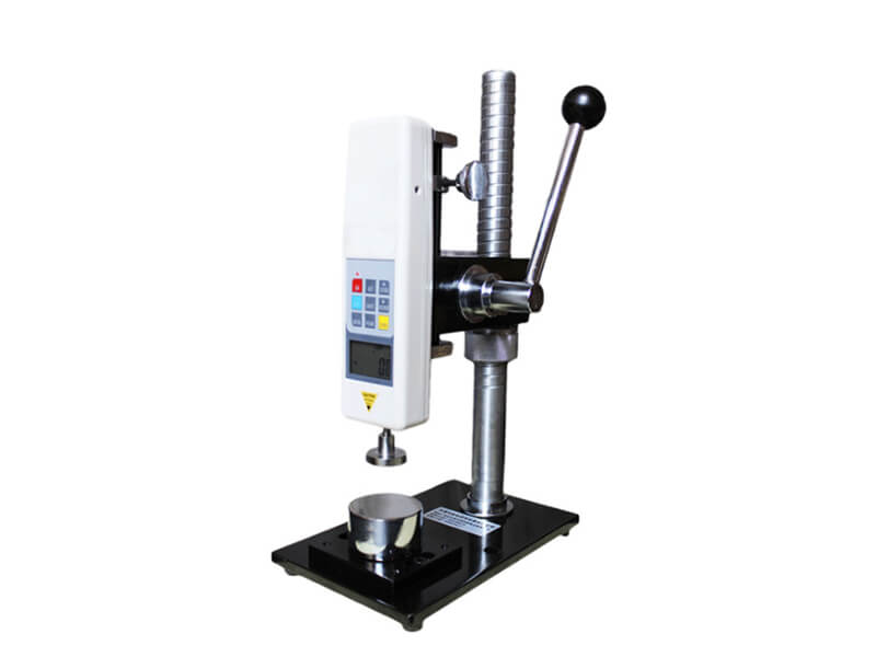
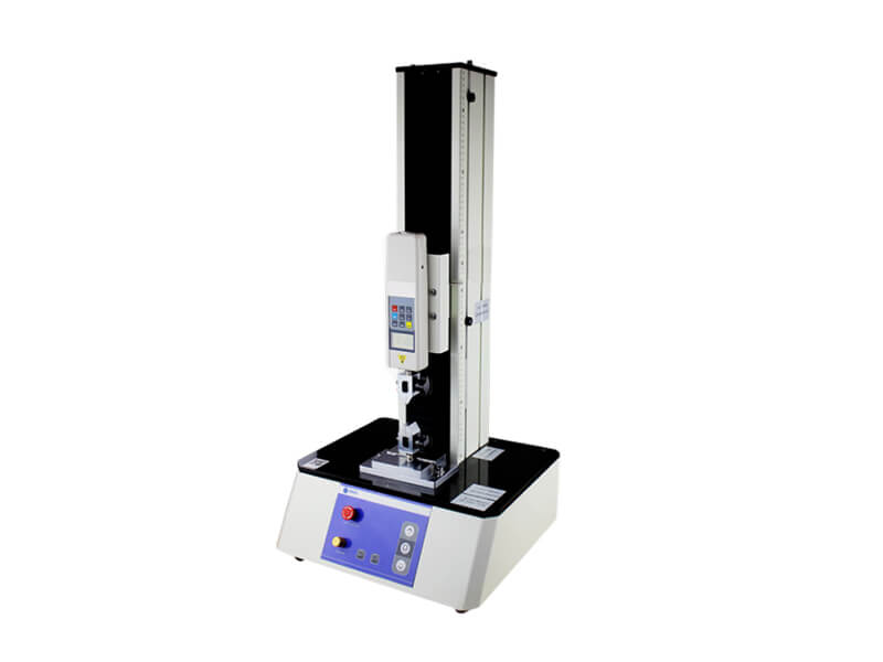
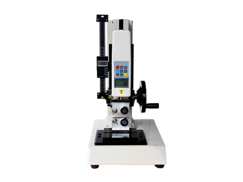
This manual push pull tester is designed to measure tensile and compression forces up to 1000 N (100 kgf). Unlike the horizontal pull test machine, which occupies a larger space, this instrument has a vertical structure. It allows specimens to be stretched perpendicularly during the test. The height of the pull tester reaches 500 mm. It is a compact tensile pull test machine, and its weight is 15 kg, so you can easily place it on the workbench for testing.
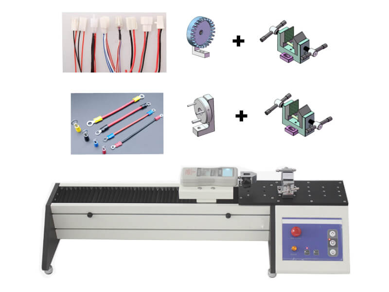
This pull test machine is a versatile instrument, especially used as the wire crimp pull tester. It can perform various tests by configuring different fixtures such as tension, compression, bending, peeling, shearing, tearing, puncture, etc.
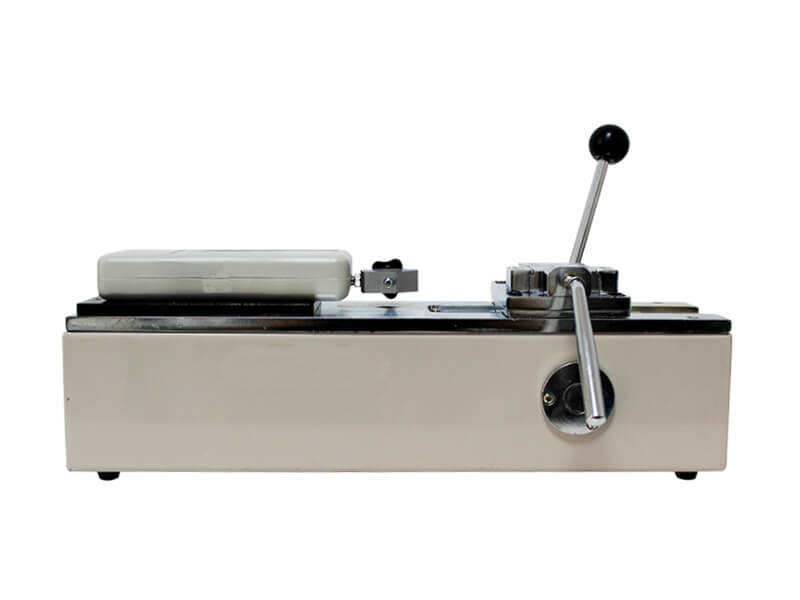
The mechanical part of the manual pull tester adopts a fully enclosed structure. The mechanical transmission system adopts high-precision ball screws and linear guides, with a tiny rotation gap and high transmission efficiency, which greatly improves the accuracy of the test. It is equipped with a handwheel in the middle of the stand. You can turn the handwheel to move the digital push-pull gauge up and down to realize the tensile or compression test on the test piece. The design of the handwheel operating part uses the principle of leverage, enabling you to operate more conveniently and labor-saving.
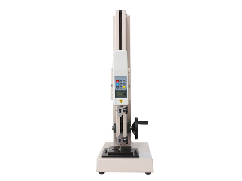
The stand of AT-U2-70 can be additionally equipped with a digital displacement scale with an accuracy of 0.01 mm, which can realize the simultaneous measurement of force and displacement and display the changes of force and displacement under each tension or compression in real-time. Please refer to the right picture of AT-U2-70B.
- AT-U2-70B
- Push Pull Tester with a Digital Displacement Scale
- Configured with a Digital Gauge
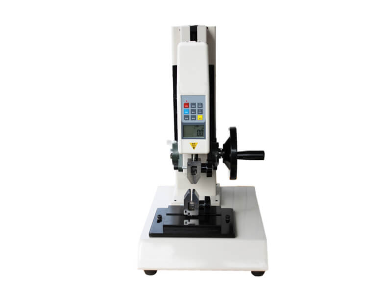
A precision digital push pull gauge is fixed to the vertical test stand of this push pull tester. It is suitable for both tensile and compression testing applications. When you turn the handwheel by hand, the push pull test gauge will also make the corresponding synchronous movement act on the sample through the upper clamp, and its total stroke reaches 150 mm.
We have push pull force gauges with an extensive measuring range from 2 N to 1000 N for you to choose from. The division values of gauges of different measuring ranges are different. The smallest is 0.0001 N. The largest is 1 N. Pull strength gauges within the maximum range of 5 N have three force value units of N / lbf / gf to be selected from. Gauges over 5 N and less than 1000 N permit you to choose any unit of Kgf / N / lbf. The force value between various units can be converted in real-time. We will configure a suitable digital gauge for you according to your testing needs while considering both practicality and economy.
The gauge has a built-in high-precision sensor responsible for real-time data collection. After the data is recorded, calculated, and counted by a particular processor, it will be displayed on the liquid crystal display of the force gauge. This screen can realize a five-digit liquid crystal display, and the direction of the display data can be inverted. It has real-time mode, peak mode and Auto peak mode to suit your different testing requirements. The gauge allows you to set the upper and lower limits freely. When the measured value exceeds the upper limit or the lower limit, there will be a flashing prompt on the screen, and the machine will beep to remind you.
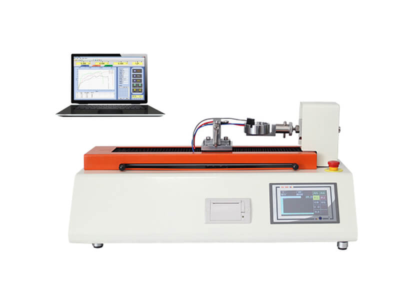
The test data can be displayed on the built-in screen with backlight function. There are 30 sets of results can be stored. We will also provide you with special software and a RS 232 data cable, which can simultaneously transmit the data to a personal computer and display the loaded force value in real-time in the form of plotting a dynamic graph. You can quickly grasp the changing trend of the force applied to the sample during the test. A built-in large-capacity rechargeable lithium battery can power the gauge of this push pull tester, or it can be directly connected to the power supply with an AC adapter to work. Data can be stored, edited, and printed.
| Operating Steps | Reference Pictures |
| 1. Mount the upper grip to the digital force gauge | 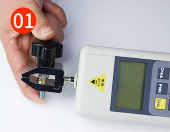 |
| 2. Remove the back plate from the test stand and install the force gauge on the back plate | 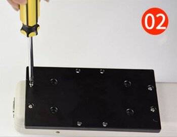 |
| 3. Install the back plate back to the test stand with screws | 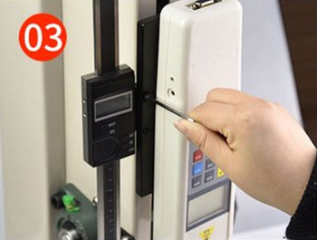 |
| 4. Insert the lower fixture hole into the rail located on the bottom plate | 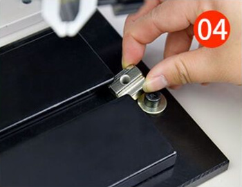 |
| 5. Fix the lower grip to the bottom plate | 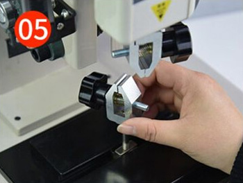 |
| 6. Clamp the specimen using the upper and lower grips to start the test | 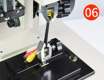 |
| Model | AT-U2-70 | |||||||||||
| Capacity | 2 N | 3 N | 5 N | 10 N | 20 N | 30 N | 50 N | 100 N | 200 N | 300 N | 500 N | 1000 N |
| 0.2 kgf | 0.3 kgf | 0.51 kgf | 1.02 kgf | 2.04 kgf | 3.06 kgf | 5.1 kgf | 10.2 kgf | 20.4 kgf | 30.6 kgf | 51.0 kgf | 102.0 kgf | |
| 0.45 lbf | 0.67 lbf | 1.12 lbf | 2.25 lbf | 4.5 lbf | 6.74 lbf | 11.24 lbf | 22.5 lbf | 45.0 lbf | 67.4 lbf | 112.4 lbf | 224.8 lbf | |
| Resolution | 0.0001N | 0.001 N | 0.01 N | 0.1 N | 1 N | |||||||
| Accuracy | ±0.5 % | |||||||||||
| Stroke | 150 mm | |||||||||||
| Units | N / lbf / gf | Kgf / N / lbf | ||||||||||
| Fixtures | A pair of fixtures corresponding to your sample (Tailored fixtures are optional) | |||||||||||
| Dimension | 360 mm ×260 mm × 500 mm (L × W × H) | |||||||||||
| Weight | About 16 kg | |||||||||||
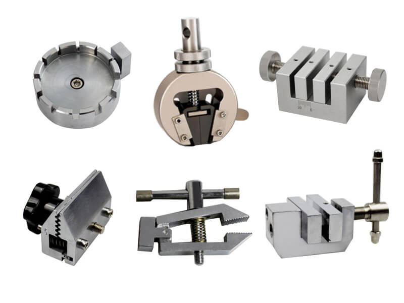
The matching fixtures and grips include but are not limited to the items listed below. If you want to learn more about the scope of testing or customize personalized fixtures, please feel free to contact us.
| Items | Reference Pictures |
|---|---|
| Sheet Specimen Grip | 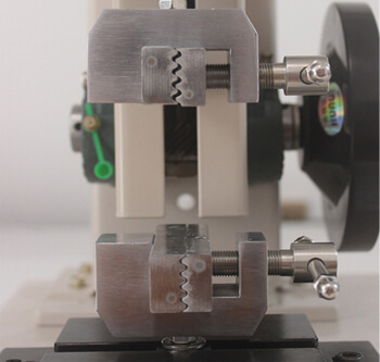 |
| Fishhook pull test fixture | 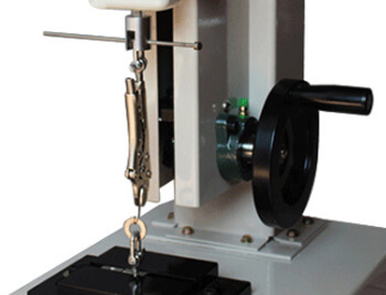 |
| FPC pull test fixture & grip | 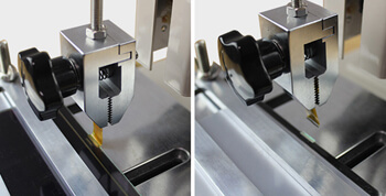 |
| Insertion force test fixture | 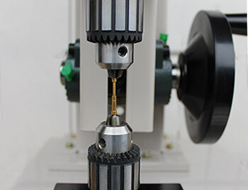 |
| Line pull test fixture | 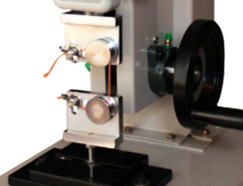 |
| Can Ring-pull Test Fixture | 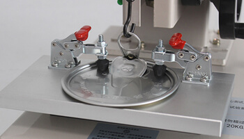 |
| Sponge compression test fixture | 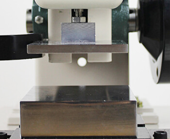 |
| Toothbrush bristle pull test fixture | 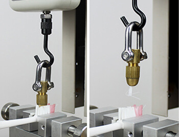 |
| Wire terminal pull test grip | 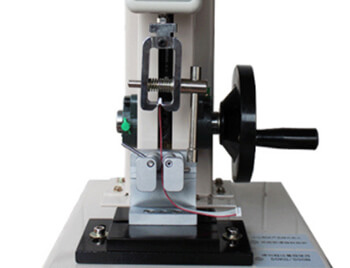 |
Please click HERE to learn more about Grips & Fixtures for selection or contact us for fixtures customized.
Send an Inquiry
Please feel free to contact us for more details on the product, price, lead time, payment terms, shipment methods, etc. Amadetech sales specialists will respond within one working day.