Extrusion Plastometer | MFI Tester China Manufacturer
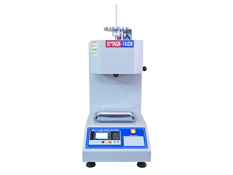
Melt Flow Indexer is also referred to as the extrusion plastometer or MFI instrument. It is intended to determine the melt flow rate of various molten thermoplastic materials extruded from the die with a specified length and bore diameter under specified conditions of temperature and load. The melt flow index tester is extensively applicable to materials with high melting temperatures, including polycarbonate, poly sulfoxide, fluoroplastics, nylon, etc., and plastics with low melting temperatures like PE, PS, PP, ABS, POM, PC, etc.
The determination of melt flow index (MFI) is divided into two methods of measuring melt mass-flow rate(MFR) and melt volume-rate(MVR). MFR is expressed by the gram per 10 minutes based on the mass of the molten material extruded from the die over the given period. MVR is expressed by the cubic centimetre per 10 minutes based on the volume of material extruded from the die over the specified period.
AmadeTech melt flow indexer features a vertical cylinder inside the top half made of wear and corrosion-resistant material. A heater surrounding the cylinder provides and maintains the required temperature for testing, and a temperature sensor is available to monitor the temperature inside the cylinder hole. A die with a bore is contained at the lower end of the cylinder hole. We equip the machine with a removable piston scribed two thin annular reference marks 30 mm apart on the stem, ensuring the distance between the lower edge of the piston head and the top of the die is 20 mm when the upper mark coincides with the top of the cylinder. You need to manually insert the piston into the heated cylinder and add the combined weights to give the material a specified load to allow the extrudate to flow out of the bore of the die.
AmadeTech can provide flexible equipment solutions. Our regular models of the melt flow index testers are capable of determining both the melt mass-flow rate (MFR) and the melt volume-flow rate (MVR). If the MVR measurement is not required during your test, A model that can only do MFR measurement is also available from AmadeTech to help you save equipment purchase costs. MFR measurement can be performed by either manual cut-off or automatically timed operation.
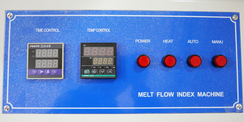
Push-button control panel
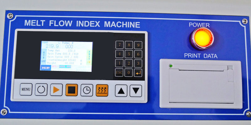
Key-type control panel
In addition, AmadeTech melt flow indexer’s control panel ranges from a traditional push-button operation panel with LED digital displays to a new key-type one with an LCD and thermal printer. You can select the corresponding model according to your preference.
If you are interested in more plastics testing instruments from AmadeTech, please click HERE.
| Model | AT-P6003 |
| Supported test methods | MFR & MVR |
| Temperature control | RT~300°C (RT~400°C & RT~500℃ are optional)
Temperature fluctuation: ± 0.5℃ Temperature uniformity: ± 1℃ Temperature display resolution: 0.1℃ Sample preheat time: 4 minutes or user-defined |
| Standard die dimensions | Φ2.095 ± 0.005 mm
Length: 8.000 mm ± 0.025 mm |
| Cylinder dimensions | Internal diameter: 9.550 mm ± 0.025 mm
Length: 152 mm ± 0.1mm Hardness not less than 500 (HV5~HV100) |
| Piston dimensions | Head length: 6.350 mm ± 0.100 mm
Head diameter: 9.474 mm ± 0.007 mm |
| Weight precision | ± 0.5% |
| Test results | Automatically calculate results and support printing |
| Material cut-off methods for MFR | Manual / automatic |
| Position displacement detection for MVR | Travel length: 30 mm
Control precision: ± 0.1 mm |
| Material cut-off time-interval | 0 ~ 999 s |
| Number of cut-off cycles | 0 ~ 999 s |
| Time display resolution | 0.1 s |
| Test Load | 8 grades in total (7 pcs of weights & a piston) |
| Power supply | AC 220V ± 10%, 50 Hz or / AC 110V ± 10% 60 Hz |
- ISO 1133 Plastics determination of the melt mass flow rate (MFR) and melt volume flow rate (MVR) of thermoplastics.
- GBT 3682-2000 Determination of the melt mass-flow rate (MFR)and the melt volume-flow rate(MVR)of thermoplastics.
- JIS K7210 Plastics Determination of the melt mass-flow rate (MFR) and melt volume-flow rate (MVR) of thermoplastics.Part 1: Standard method.
The specimen in a specified quantity is placed in the barrel of the melt flow tester and heated to reach a molten state under the specified temperature condition. The melt is extruded from a die of a specified length and diameter under a prescribed load. For MFR, timed segments of the extrudate are weighed, and the extrudate rate is calculated in g/10m. For MVR, the time required for the piston to move a specified distance is measured to generate a result in cm3/10m.
AmadeTech MFI Tester Features
- Made of hard material in line with standard requirements.
- Supports MFR & MVR measurements (for regular models).
- Fitted with an LCD to assist in parameter setting and show the real-time running state (for regular models).
- Has flexible temperature options, and the maximum is as high as 500°C.
- A dual temperature control system allows more accurate temperature control and higher heating efficiency.
- Equipped with a spatula to manually & automatically cut off the extrudate.
- Provided with an encoder to record the piston displacement automatically, the system can measure the times taken.
- Multiple weights in different levels are provided to enable different combined loads.
- Able to calculate test results automatically, and printing on-site is available.
FAQs
MFR is short for Melt Mass-flow Rate, which is the mass of the molten materials extruded from the die bore per 10 minutes under the specified temperature and pressure conditions, expressed in g / 10 min.
MVR is short for Melt Volume-flow Rate, which is the volume of the molten materials extruded from the die bore per 10 minutes under the specified temperature and pressure condition, expressed in cm3 (ml) / 10 min.
Let’s use ISO 1133 as an example to briefly describe the melt flow index testing process using AmadeTech extrusion plastometer.
Procedure A: Mass-measurement method (for MFR)
- A1. Mount the die from the top of the cylinder and press it with the packing rod until it contacts the die retaining plate, then put the piston rod into the cylinder.
- A2. Turn on the power switch on the control panel, and the power indicator light will be on. Press 1 to enter the MFR test interface. Press the “HEAT” button to turn on the machine heating function, then set an intended test temperature, extrudate cut-off time interval, and the number of sampling times.
- A3. Stabilize the temperature of the cylinder for additional 15 minutes after the pre-determined temperature of the cylinder is reached.
- A4. Put on the included gloves, and take out the piston, then charge the bore of the cylinder with the specified mass of the specimen material. During charging, compress the specimen with the packing rod using hand pressure to enable it to be as free from the air as possible. The whole charging process should be completed within 1 minute.
- A5. Immediately put the piston back into the cylinder (you can unload or underload the piston depending on the test needs), then press the “Countdown” button to start the timer for preheating the specimen.
- A6. At the end of the preheat period, apply the required load to the piston from the top to allow the piston to descend under gravity.
- A7. Observe the position of the piston stem. When the lower reference mark is aligned with the top edge of the cylinder, press the “START” button to initiate the spatula to cut off the extrudate in a row based on the preset time interval and discard the previous material during the preheat period.
- A8. When the upper mark on the piston stem reaches the top edge of the cylinder, press the “STOP” button to stop the test.
- A9. After the sampling is completed, let the excess material in the cylinder automatically flow out under gravity or compress the piston by hand to let the excess material flow out. After the excess material has flowed out, remove the piston and clean it with gauze. Pull the knob on the machine side to release the die from the cylinder and clean it with the corresponding tools. Take the gauze with a length of about 120 mm, fold it into three layers, then put it on the charging hole of the cylinder, and then use the packing rod to thrust against the gauze through the cylinder to the bottom to get rid of the remains by turning it up and down and rotating it left and right.
- A10. Collect successive cut-offs and discard all ones containing visible air bubbles. After cooling, weigh them individually with a balance to the nearest 0.001 g and calculate their average mass.
- A11. Input the load value and average extrudate mass in a specified time interval into the machine, and the MFR is obtained automatically. Press “ENTER” to print out the test results if necessary.
Procedure B: Displacement-measurement Method (for MVR & MFR)
Because most steps of Procedure B are the same as that of Procedure A, here we will not repeat the above steps. Just mention the differences:
- B2. After turning on the machine, you need to press “2” to enter the MVR test interface, then set an intended test temperature and a time interval beyond the overall test time to disable the automatic cut-off function.
- B5. A displacement encoder is required to be added below the piston barrier to automatically record the time taken for the piston to descend 30 mm.
- B7. Press the “START” button before the piston barrier contacts the detection tip of the displacement measuring device. The system will automatically complete the test and show the MVR. MFR is also can be obtained after inputting the melt density of the specimen.
- The melt flow index calculation formula for MFR is as below:
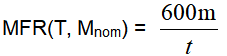
Where,
T is the test temperatrure, in degree Celsius;
Mnom is the nomianl load, in kilograms
m is the average mass, in grams, of the cut-offs;
t is the cut-off time-interval, in seconds;
600 is the factor used to convert grams per second into grams per 10 min
- The MVR also can be calculated based on the MFR using the following formula:
MVR = MFR/Melt density of the material
- The melt flow index calculation formula for MVR is as below:
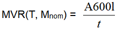
Where,
T is the test temperature, in degree Celsius;
Mnom is the nominal load, in kilograms;
A is the mean of the cross-sectional areas of the cylinder and the piston head, in square centimeters;
t is the predetermined time of measurement or the mean value of the individual time measurements, in seconds;
l is the predetermined distance moved by the piston or the mean value of the individual distance measurements, in centimeters
- The MFR also can be calculated based on the MVR using the following formula:
MFR(T, Mnom) = MVR x ρ
Where,
ρ is the density of the melt at the test temperature, in grams per cubic centimeter, is given by the equation

There are 2 factors to be considered during the test:
1. Test temperature acting on the polymer melt
Generally, the higher temperature causes an easier flow of the polymer melt, achieving a high value of MFR, but it also depends on the situation. Taking polypropylene as an example, if the temperature is too low and the melting state is not complete, the MFR measurement must be too small. If the temperature is too high, above 260 degrees, polypropylene will begin to oxidize and degrade, and the large molecules will become smaller and melt. The fingers must be bigger, but that would not be very meaningful.
High uniformity of the testing machine cylinder temperature is also required. If the temperature distribution in the cylinder is uneven, it will bring obvious uncertainties to the flow rate test results.
2. Load applied to the polymer melt
The load is proportional to the melt flow rate of the polymer melt. The higher the force, the higher the shear force and shear rate applied to the melt, which generates lower viscosity and a higher melt flow rate. An appropriate load is required during the test to indicate the objective properties of materials.
Method A of ISO 1133 specifies that a few segments of extrudates cut off successively in a given piston travel are required. Although our melt flow index tester supports manual and automatic operations, the automatic mode of cutting off the extruded melt according to the preset time interval and the number of cycles is more popular.
If this process is operated manually, there will be errors in grasping the time interval. At the same time, if the flow rate is too high, the test personnel will not have time to cut at all. And if it is a very low rate, it takes half an hour or even longer to cut one time, and the labor intensity of the operator is very large. Therefore, Choosing the automatic mode is necessary.
The melt index test result is a core indicator of judging how well polymers flow under specified conditions. The MFI test has a positive impact on the plastic industry.
Material Identification
The MFI test helps in identifying the molecular weight and molecular weight distribution of the thermoplastic polymer, as well as the flow characteristics and processing behavior.
In fact, the melt flow rate helps analyze the relative values of material properties, predicting the relative ease with which resin will flow during processing. MFI is inversely proportional to molecular weight. As molecular weight increases, the melt flow rate decreases, and vice versa. The strength of the polymer is related to the molecular weight so MFI can be used as an indicator of the strength of the polymer.
Material Selection
After recycling waste plastics, plastics are reprocessed into shapes. The primary reference is the melt index because the fluidity of plastics determines some properties of materials, such as tensile strength, elongation, elastic modulus, and other parameters.
Quality Control
In mass production, different products of the same batch need to be sampled to check whether their melt flow index is stable within a range so as to determine whether the batch of materials is a qualified product. For the same batch number and different batches of incoming materials, the melt flow index can also be compared to determine the stability of the incoming materials.
The MFI test can also evaluate any changes or degradation in the materials.
If the MFI is large, the flow of the material is high, the molding process is convenient, and the rigidity property is good. However, the performance of the processed products is poor, and cracking will occur later. With the increase in melt flow rate, tensile strength, tear strength, stress crack resistance, heat resistance, weather resistance, impact strength, and shrinkage, all will decrease.
If the MFI is small, the fracture strength, hardness, toughness, aging resistance, and other properties of the processed products will be high. However, the injection molding will be affected because the flow rate is too slow during injection molding. At this time, it is necessary to increase the temperature or pressure during injection molding.
| Total load(kg) | 0.325 | 1.200 | 2.160 | 3.800 | 5.000 | 7.160 | 10.000 | 12.5 | 21.6 |
| Piston(kg) | 0.325 | 0.325 | 0.325 | 0.325 | 0.325 | 0.325 | 0.325 | 0.325 | 0.325 |
| Weight(kg) | – | 0.875 | 1.835 | 3.475 | 4.675 | 1.835
5.000 |
4.675
5.000 |
2.500
4.675 5.000 |
0.875
1.835 2.500 2.915 3.475 4.675 5.000 |
Our melt flow index tester can accept any form that can be introduced into the cylinder bore, such as granules, strips of film, powder, or sections of moulded or extruded parts.
Leave Your Message Here
Please feel free to contact us for more details on the product, price, lead time, payment terms, shipment methods, etc. Amadetech sales specialists will respond within one working day.