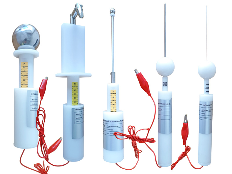
IP1X/2X/3X/4X Test Probes China Manufacturer
IP Test Probe Kit is a set of tools used to determine the degrees of protection provided by product enclosure against access to hazardous parts and ingress of solid foreign objects. It consists of access probes and object probes, which are required to be pushed against or inserted through any openings of the enclosure with the specified forces during testing. The access probes are used to simulate in a conventional manner a part of a person or a tool held by an operator to confirm whether there is sufficient clearance from hazardous parts. The object probes are applied to simulate solid foreign objects to confirm the possibility of ingress into an enclosure.
AmadeTech IP test probes are made of insulating nylon material and stainless steel. Each of the test probes is equipped with a wire and an alligator clip to connect to the hazardous parts inside the enclosure conveniently when testing on low-voltage equipment. This signal-circuit method requires an additional low-voltage supply and a suitable lamp, which are available from AmadeTech If needed. During the test, you can accurately determine whether the test probe and hazardous parts are in contact by observing whether the light is on. Alternatively, Measuring the resistance between the test probe and the live parts with a multimeter to check for a loop can achieve the same purpose during the test.
Power supply
Except IP2X requires the use of a Jointed test finger to carry out the test for protection against access to hazardous parts and the sphere of 12.5 mm in diameter to conduct the test for protection against solid foreign objects, for other IP1X, IP3X, and IP4X, the one test level for assessing the protection against hazardous parts and solid foreign objects can share one test probe. IP4X test probe can also be used for IP5X and IP6X protection tests against hazardous parts.
If you require more IP testing equipment for dust and water resistance tests, please click HERE to learn more.
Item | Schematic Diagram | Parameters | Applications | Physical Picture |
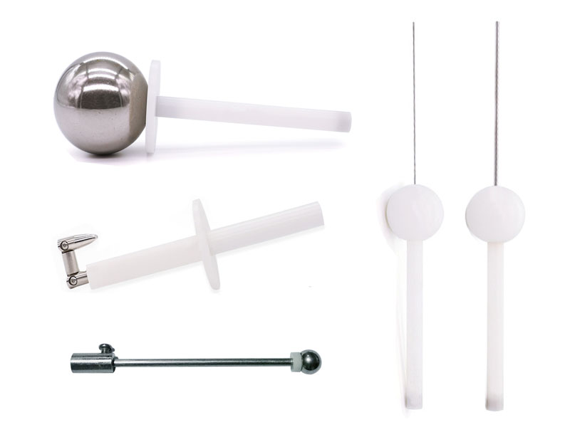
IP1X test probe - 50.0 mm diameter sphere | 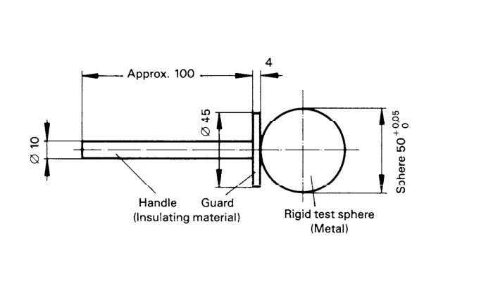 |
| Test for protection against access to hazardous parts & solid foreign objects required by IP3X or IPXXA | 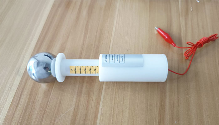 |
IP2X access probe - Jointed test finger | 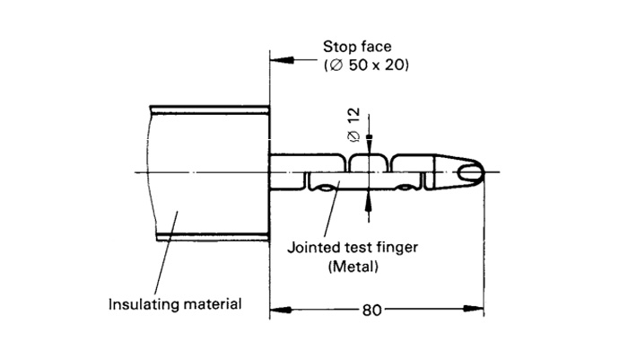 |
| Test for protection against access to hazardous parts required by IP2X or IPXXB | 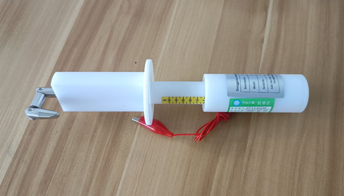 |
IP2X object probe - 12.5 mm diameter sphere | 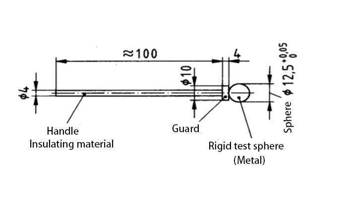 |
| Test for protection against Solid foreign objects required by IP2X | 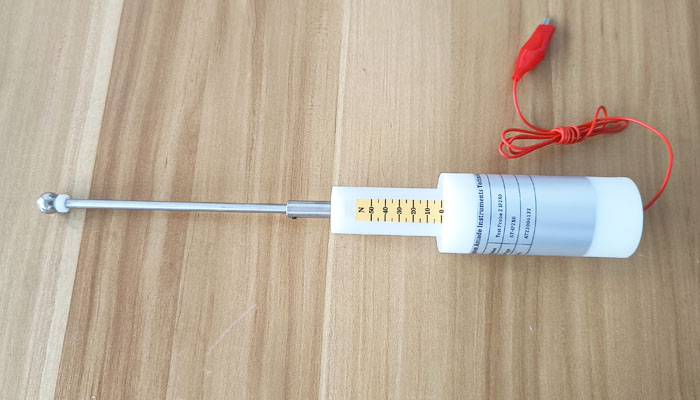 |
IP3X test probe - Test rod | 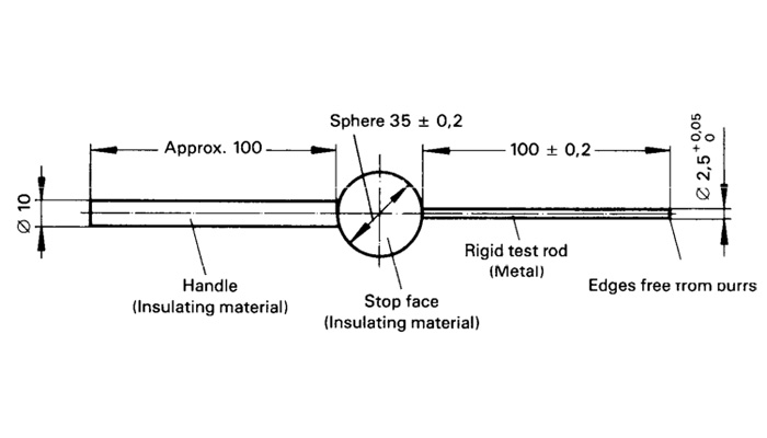 |
| Test for protection against access to hazardous parts & solid foreign objects required by IP3X or IPXXC | 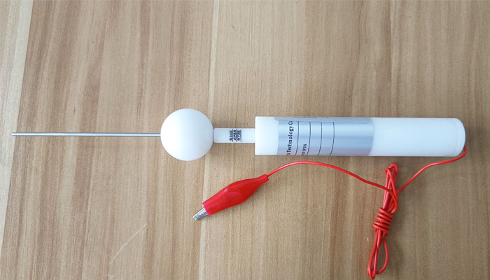 |
IP4X test probe - Test wire | 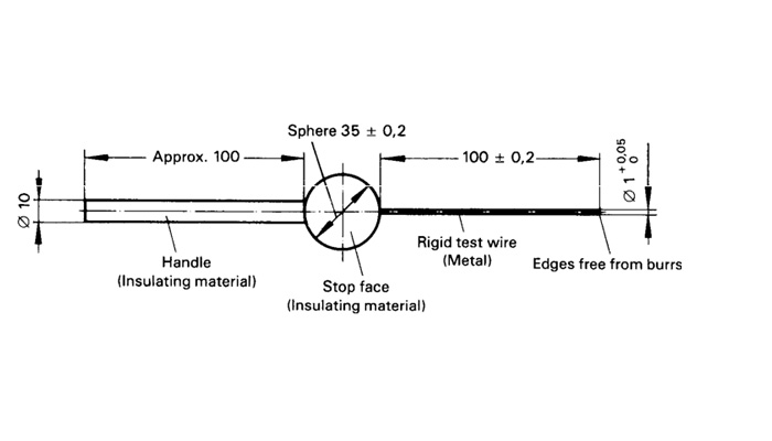 |
| Test for protection against access to hazardous parts required by IP4X, IP5X, and IP6X or IPXXD | 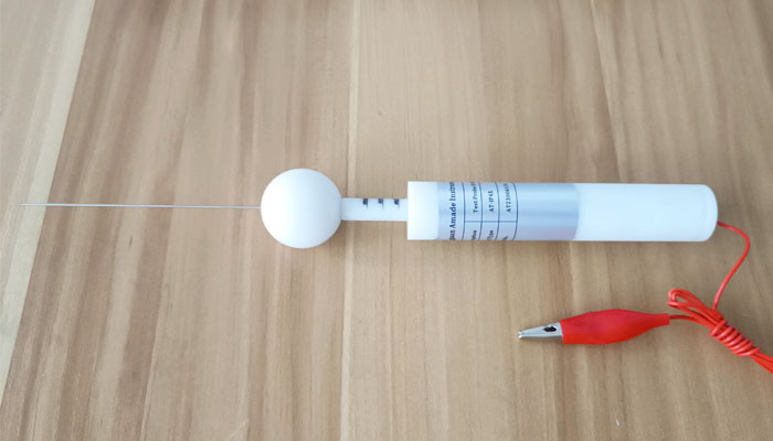 |
Difference Between the AmadeTech IP Test Probes with and Without the Thrust Indicator
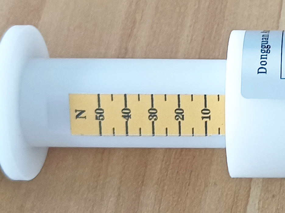
In terms of the means to measure the test force applied to the enclosure, AmadeTech can provide test probes with or without the thrust self-measuring systems. The system consists of a 2-in-1 sleeve-type handle and a spring device built into the handle, allowing the probe’s front-end metal part to extend and shorten back and forth as the force applied against the enclosure changes. The graduations of desired force values are marked on the surface of the thinner handle at the front, such as 30 N, 10 N, 3 N, etc. The force values corresponding to the graduation positions are obtained through calibration using a professional measuring instrument.
Taking into account the influence of the test probe’s own weight on the force application in different test directions during testing, for the IP3X and IP4X probes whose test force is not large and easy to be interfered with, we calibrate and mark the same force in three directions: up, down, and horizontally. Three different graduations on the handle facilitate you to perform the test from different directions and enhance the accuracy of the applied force during the test.
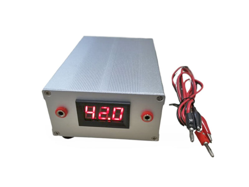
If you don’t want the test probes with the thrust indicator, test probes without the thrust self-measuring system are also available from AmadeTech. In order to ensure that the force applied meets the requirements of relevant standards during testing, you must prepare an additional push gauge (refer to the right figure). During the test, you need to hold the test head vertically against the tail of the IP test probe (or connect both securely with the M6 screw) and slowly push forward to apply force while observing the force value display window until it reaches the specified value.
Probes without thrust indicators
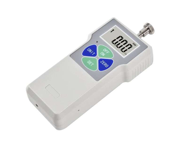
Digital push gauge
FAQs
Request a Quote Now
Please feel free to contact us for more details on the product, price, lead time, payment terms, shipment methods, etc. Amade Tech sales engineers will respond within one working day.