Servo Hydraulic Universal Testing Machine
- AT-U2-WAW series
- Capacity: 100 kN, 300 kN, 600 kN, 1000 kN or customized
- Control mode: Closed-loop
- Automatic Loading
- Computer + Special Software
- Suitable for Tensile & Compression Testing
Manual Hydraulic Universal Testing Machine
- AT-U2-WE series
- Capacity: 100 kN, 300 kN, 600 kN, 1000 kN or customized
- Control mode: Open-loop
- Manual Loading
- Microprocessor + Digital Display
- Suitable for Tensile & Compression Testing
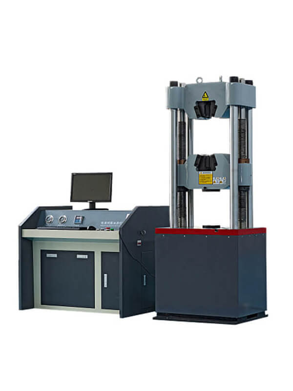
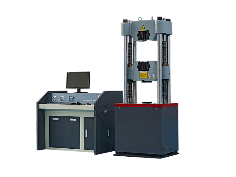
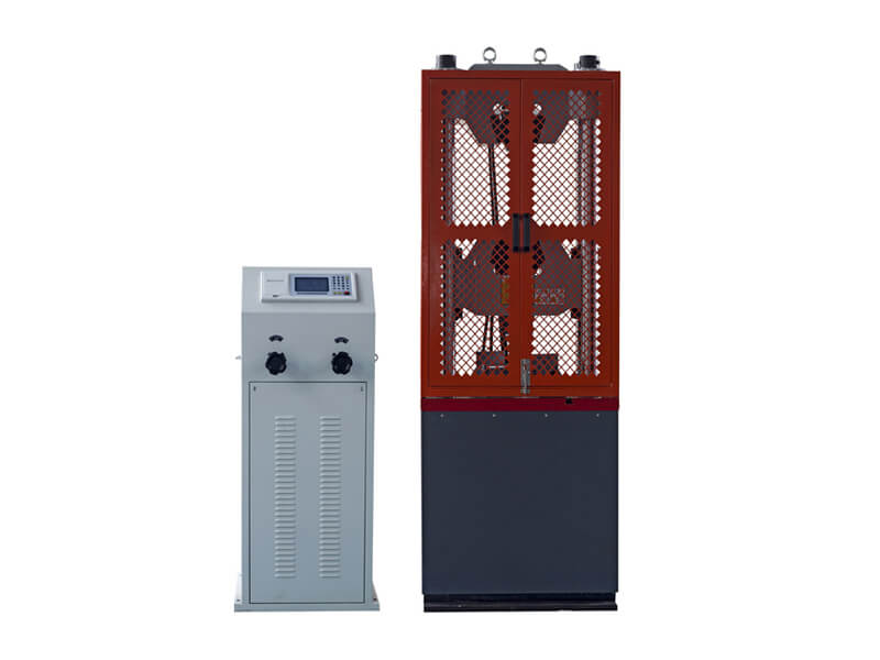
Servo Hydraulic Universal Testing Machine
Servo Hydraulic Universal Testing Machines is a material testing machine using computer fully automatic closed-loop control. It is mainly used for the tensile, compression, flexural, shear, and other mechanical performance tests of metal materials. After the corresponding attachments are added, they can also be applied to tests on concrete, bricks, tiles, and other materials.
The servo-hydraulic testing machine is suitable for steel metallurgy, building materials, aerospace, and other industries for quality inspection, material research and development, teaching, and scientific research. It complies with the requirements of ISO, ASTM, GB, DIN, and other standards.
The Servo Hydraulic universal testing machine has a closed-loop servo control system composed of a controller, a servo valve, a force sensor, a displacement sensor, an extensometer, and a computer. It is able to automatically and accurately control the test process and set up the test parameters to achieve three-stage control of force, displacement, and deformation during the test. This hydraulic universal testing machine allows for constant velocity stress, constant velocity strain, constant velocity displacement, displacement retention, and test force retention.
Each set of the hydraulic universal testing machine is equipped with unique measurement and control software to assist in completing the operation and control required for various tests. The computer displays various data and required test curves in real time and automatically calculates and analyzes test results to obtain specific values. The test report and test curve can be saved and editable.
WAW Series Servo Hydraulic Universal Testing Machines have various measuring capacities, including 100 kN, 300 kN, 600 kN, 1000 kN, and more for you to choose from. They are equipped with a high-precision force transducer, displacement transducer, and extensometer. The load force is not divided in the whole process, and the effective range is 2% ~ 100 FS. The force resolution is 1/300000, and the test force measurement accuracy is better than ± 1 % of the indicated value. The displacement resolution is 0.01 mm, and the measuring range is 0 ~ 250 mm. The displacement accuracy is better than ± 1 % of the indication. The gauge length of the standard electronic extensometer is 50 mm, and the deformation measurement range is 0 ~ 15 mm. The deformation measurement accuracy is better than 0.5 % of the indicated value.
The oil in the oil tank is driven by the oil pump motor into the hydraulic oil circuit, flows through the high-pressure oil filter, the differential pressure valve group, and the servo valve, and then enters the working oil cylinder. The computer software sends a control signal to the servo valve to control the opening of the valve and the direction of the oil flow to control the actual flow into the working cylinder to adjust the loading speed and state of the fixture to the sample, and realize the control of the constant velocity test force, constant velocity displacement. The strain measurement is executed by a built-in displacement measuring device or an external extensometer.
| Model | AT-U2-WAW series |
| Capacity | 100 kN / 300 kN / 600 kN / 1000 kN or customized |
| Effective Measuring Range of Load | 2 ~ 100 % F.S |
| Load Resolution | 1/300000 |
| Load Accuracy | Better than 1 % the indicated value |
| Measuring Range of Displacement | 0 ~ 250 mm |
| Displacement Resolution | 0.01 mm |
| Displacement Accuracy | Better than 1 % the indicated value |
| Gauge Length of Extensometer | 50 mm |
| Effective Measuring Range of Deformation | 2 ~ 100 % F.S |
| Deformation Resolution | 1/300000 |
| Deformation Accuracy | Better than 0.5 % the indicated value |
| Piston Stroke | 250 mm |
| Computer | Based on Windows Operating System |
| Control Mode | Three closed-loop control (constant stress, constant strain and constant deformation) |
| Test Speed | Up to 70 mm / min |
| Electrically Adjusted Speed of Crossbeam | Up to 120 mm / min |
| Max Vertical Test Space Between Tensile Grips | 650 mm |
| Max Vertical Test Space Between Compression Platens | 550 mm |
| Front Column Spacing | 540 mm |
| Widget Grips for Tensile Test | For Round specimens from Φ6mm~Φ40mm |
| For flat specimens from 0 ~ 30 mm in thickness, 75 mm in width | |
| Platens for Compression Test | Φ160 mm (Square platens are optional) |
| Attachments for Flexural Test | Roller spacing: 30 ~ 600 mm
Width: 140 mm Roller diameter: 30 mm |
| Power Supply | AC 380 V / 50 Hz / 3-phase |
Load Frame
The load frame is mainly composed of a workbench, columns, a fixed crossbeam, a movable crossbeam, lead screws, fixtures, a working cylinder, a piston, and so on.
General Structure
Our servo hydraulic machines feature a four-column structure (two lead screws are not included). The columns made of precision steel are connected by a fixed crossbeam at the top to ensure sufficient strength as required. The testing area adopts a dual-space structure, and the working cylinder is located at the bottom of the frame. The tensile space of conducting the tension and shearing tests is between the upper crossbeam and the middle movable crossbeam. The space for the compression and bending is between the workbench and the middle movable crossbeam.
Both the tensile and compression spaces can be automatically adjusted by the rotation of the lead screws driving the middle crossbeam to move up and down. Thanks to this design, the operator can easily and quickly switch between the two completely different test types in tension and compression during testing, avoiding extra time and labor to replace bulky fixtures and improving the test efficiency.
The working oil cylinder and piston are located at the bottom of the frame. The pressure oil is sealed by the oil film between the cylinder and the piston and guided by the inner surface of the cylinder. A complete set of the cylinder drive mechanism is available to realize the rotation of the lead screw. The screw can rotate in both directions to drive the crossbeam to move up and down.
The adjustment of the size of the test space (the distance between the fixtures) before the test is driven by a built-in electric motor in the base instead of hydraulically. This motor is controlled by special adjustment buttons on the control cabinet or the remote control hand set. It is only used to quickly adjust the up and down positions of the moving crossbeam when it is unloaded and will not exert any force on the specimen during the test.
Fixtures & Attachments
We will configure three different fixtures or accessories for the hydraulic testing machine for the tensile, compression, and flexural tests.
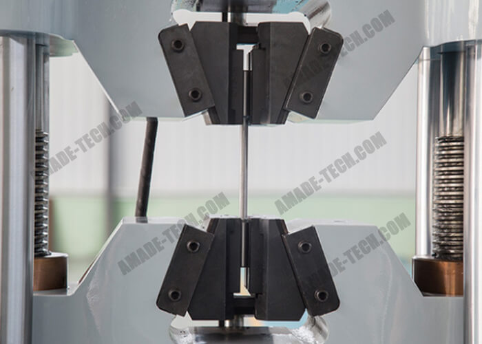
Hydraulic Wedge Fixtures
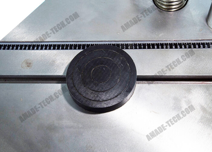
Compression Platens
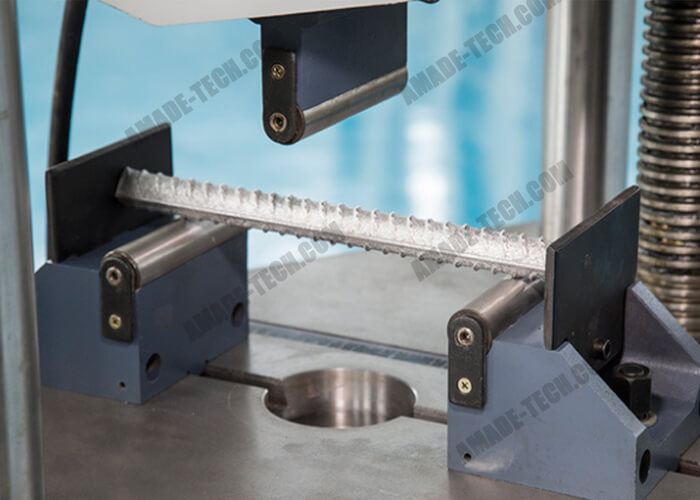
3-point Flexural Test Fixtures
Hydraulic Wedge Fixtures
This hydraulic universal testing machine comes with a pair of hydraulic wedge fixtures. They are capable of clamping the sample automatically by hydraulic. Each gripping device contains two different types of jaws to accept round samples from 6 to 40 mm in diameter, and flat samples from 0 to 30 mm in thickness and up to 75 mm in width (depending on the machine’s capacity).
Platens for the Compression Test
This hydraulic testing equipment is fitted with two platens made of rugged metal for compressive testing. The diameter of both is 160 mm. One is mounted to the middle of the bottom of the movable crossbeam. The other one is attached to the workbench.
Fixtures for the 3-point Flexural Test
A set of unique fixtures consisting of 2 parts are available for the flexural test. The compression space below the crossbeam is needed to do this test. The strip sample is placed horizontally on two rollers of the lower fixture fixed to the workbench. The width of these two rollers is 140 mm, and their spacing is adjustable between 30 and 600 mm.
During the test, along with the downward movement of the movable crossbeam, the roller of the upper fixture fastened to the crossbeam’s bottom was required to touch the middle of the two rollers on the workbench and continuously load onto the specimen. The diameter of the three rollers on the fixtures is 30 mm.
Control Unit
The WAW series hydraulic tensile testing machines are equipped with the Servo valve and PID control, ensuring all tests are under load and displacement controls. According to the feedback signal, the control system will automatically control the amount and speed of oil supplied to the working cylinder.
After the test is completed, the test results such as the maximum force, tensile strength, yield strength, elastic modulus, and elongation after fracture of the material are automatically obtained. Unlike the manual hydraulic universal testing machine requiring you to manually adjust the oil supply to the working cylinder during the test to control the load, for this servo-hydraulic universal testing machine, you only need to preset the necessary parameters before testing and then send the test machine a start command.
The machine will automatically complete all steps during the entire test process. It can save you time, worry, and effort.
Computer Control
A computer installed with special software is required to connect with the machine. This servo-hydraulic universal testing machine’s operation on the data acquisition, analysis, control, presentation, statistics, storage can be completed via the computer.
The software has very clear navigation prompts and a humanized operation interface. After opening the software, you can select your test type, including tensile test, compression test, and flexural test. There are many different specific test items preset in each test type for you to choose. The main test objects of these test items are the samples of steel and mortars.
Before the test, the system allows you to customize the test group number and the number of test pieces. Different test types will require you to enter specified parameters, such as the diameter and cross-sectional area of the sample. When you do a constant load test, you can customize the constant load, the duration of the constant load, the loading time, and the loading rate.
When you start the test, various real-time vales will be displayed on the computer screen, such as force value, loading velocity, maximum force value, displacement, displacement velocity, maximum displacement, extension value, etc.
The real-time data of the test can also be expressed in the form of a curve on the computer screen. The abscissa and ordinate can be set to represent different parameters to generate different graphs including “force-time”, “force-deformation”, “strain-elongation”, “force-displacement”, “displacement-time”, etc. In this way, you can easily observe changes and trends of various data in the test process.
All test data can be stored, viewed, and recalled. The test result can support on-site printing (Another printer is required). Start, stop, reset, pause, return, the rise and fall of the oil cylinder can be easily controlled on the computer software with the mouse.
Hand-held Remote Control
In order to facilitate the user to adjust the distance of the test space and clamp the sample, we have equipped this Servo Hydraulic Testing Machine with a remote control hand set connected to the machine by a cable. It features a compact size and a light weight. A few keys are distributed on the front panel.
There are 4 keys responsible for the opening and closing of Jaws in the upper jig and the lower jig. When you stand by the machine and want to put the sample into the jaws, you only need to press the corresponding button once, and the fixture will automatically grip the sample according to your instructions.
There are also two keys on the remote control used to control the motors responsible for moving the movable crossbeam up or down. You only need to long press one of them, and the fixture connected to the moving beam can rise or fall to your desired position to match your mounting of the specimen.
Extensometer
If you have a high requirement for strain measurement of the specimen, the extensometer is recommended. Different types of extensometers with various accuracy are available here. We will provide you with an electronic extensometer with a gauge length of 50 mm as standard. The range is 0 ~ 15 mm. Please advise us of your other special requirements. Our sales engineers will submit a solution to you.
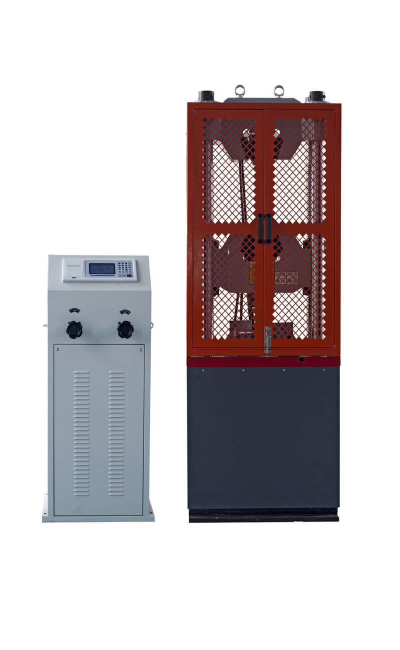
Manual Hydraulic Universal Testing Machine
Manual Hydraulic Universal Testing Machine is an economical solution of using hydraulic power source equipment to perform tensile, compression, bending, shear tests on metal or non-metal samples. This hydraulic universal test machine is characterized by the open-loop control requiring hand operation to apply the load to the specimen through the oil delivery valve. It has a manual oil supply valve and a manual oil return valve to adjust the amount and speed of oil supplied to the working cylinder.
The manual Hydraulic Tensile Testing Machine is widely used in metallurgy, construction, aviation, aerospace, and other fields for product performance evaluation, quality inspection, and new product research and development.
The oil in the tank is sucked into the oil pump through the oil filter net and then sent to the oil supply valve through the oil delivery pipe of the oil pump. When the oil delivery handwheel is closed, the oil flows from the oil return pipe to the oil tank. When the oil delivery handwheel is turned on, the oil enters the working oil cylinder through the oil pipe to drive the lead screw to rotate and cause the moving crossbeam to move up and down. At the same time, the oil is synchronously acted on the pressure sensor through the pressure oil pipe, and the sensor signal is converted and processed by the microcomputer measurement and control system to indicate the test force value.
| Model | U2-WE-100 | U2-WE-300 | U2-WE-600 | U2-WE-1000 | ||
| Capacity | 100 kN | 300 kN | 600 kN | 1000 kN | ||
| Effective Measuring Range of Load | 2 ~ 100 % F.S | |||||
| Load Resolution | Better than 1 % the indicated value | |||||
| Piston Stroke | 250 mm | |||||
| Control Mode | Manual | |||||
| Max Vertical Test Space Between Tensile Grips | 650 mm | |||||
| Max Vertical Test Space Between Compression Platens | 550 mm | |||||
| Front column spacing | 540 mm | |||||
| Acceptable Diameter of Round Specimens for the Tensile Test | 6 mm ~ 26 mm | 13 mm ~ 40 mm | ||||
| Acceptable Thickness of Flat Specimens for the Tensile Test | 0 ~ 15 mm | 0 ~ 30 mm | ||||
| Utmost Width of Flat Specimens for the Tensile Test | 75 mm | |||||
| Diameter of Round Platens for Compression Test | 160 mm | |||||
| Attachments for the Flexural Test | Roller spacing of the lower attachment: 30 ~ 600 mm
Width of the roller: 140 mm Diameter of the roller: 30 mm |
|||||
| Power | AC 380 V / 50 Hz / 3-phase / 5 lines | |||||
| Dimension of the Load Frame | 810 × 560 × 2050 mm | 810 × 560 × 2050 mm | 880 × 580 × 2150 mm | 1060 × 660 × 2450 mm | ||
| Dimension of the Control Cabinet | 580 × 550 × 1280 mm | 580 × 550 × 1280 mm | 580 × 550 × 1280 mm | 580 × 550 × 1280 mm | ||
| Weight | 1500 kg + 320 kg | 1800 kg +320 kg | 2100 kg + 320 kg | 2800 kg +320 kg | ||
Load Frame
There are two columns and two lead screws on the bench of the load frame. The tops of the columns are connected by a fixed cross head to form a rigid frame. The column is made of precision steel to ensure that it has enough strength to bear the force during the tensile test.
There is a cross head supported by lead screws at both ends, which can move up and down. It divides the test space of the load frame into two. The upper space of the moving cross head is used for tensile testing, and the lower space of the moving cross head is used for compression and bending testing. The test area is equipped with a special protective cover to protect the operator from preventing injury when the sample breaks.
The two spaces do not interfere with each other during the test. You can do these two tests directly, one after the other, without changing the fixture. It significantly saves you time and energy and improves test efficiency. Because these fixtures are cumbersome, replacing them is not so easy.
The working cylinder of this machine is located in the lower part of the load frame. The cylinder and piston are the main parts of the drive unit. Their contact surfaces are precisely processed, and a specific clearance and proper oil film are maintained. Therefore, special attention should be paid to the cleanliness of the oil during use. Do not allow impurities and iron filings in the oil to enter the working cylinder through the oil pump, oil valve, oil pipe, etc., which will damage the contact area of the cylinder and the piston, thereby affecting the accuracy of the test.
Control Cabinet
The shell of this hydraulic universal test machine’s control cabinet adopts complete plastic spraying treatment to prevent rust and moisture. There is a digital LCD on the top operation panel that can display the loading rate, loading force value, peak value, test curve, and other information in real time during the test.
The display interface includes the test method selection interface, the test parameter selection interface, the test operation, and result display interface, and the curve display interface. In addition, there are various touch keys next to it to assist you in setting various test parameters. The power button and indicator light and the on-off button of the high-pressure oil pump motor are located on the operation panel.
After the test is completed, the test results such as the maximum loading force, tensile strength, and yield strength rate are automatically obtained. Test data can be stored. The built-in thermal printer supports result printing.
On the front side of the control cabinet, the two manual valves are the most conspicuous. One is the oil supply valve (oil delivery valve), also known as the load & speed control valve. The operator manually rotates and opens this valve to allow the oil pump to output high-pressure oil into the working cylinder of the hydraulic testing machine to drive the moving cross head on the load frame to move up and down. At the same time, it can control the speed at which the force value increases. The other is the oil unloading valve (oil return valve). After manually turning this valve open, the oil in the working cylinder will flow back to the oil tank to unload the load.
The oil supply valve plays a critical role in the entire test process. During the hydraulic loading process, the operator needs to adjust the oil supply volume and oil supply rate based on real-time data displayed on display.
The oil tank is located inside the control cabinet. There is an oil window outside the oil tank to observe the oil level. The high-pressure oil pump is directly connected with the motor and installed on the oil tank cover. The high-pressure oil pump is an axial plunger pump composed of seven sets of piston pairs. The piston and sleeve in the oil pump have high surface quality and good cooperation, which ensures the possibility of high-pressure production and minimizes the oil leak.
Fixtures & Attachments
Same as the servo-hydraulic universal testing machine, we also configure three different fixtures for this manual hydraulic testing machine to enable it to perform tensile, compression, and flexural tests. Please check the above according part for more details.
Send an Inquiry
Please feel free to contact us for more details on the product, price, lead time, payment terms, shipment methods, etc. AMADE TECH sales specialists will respond within one working day.